
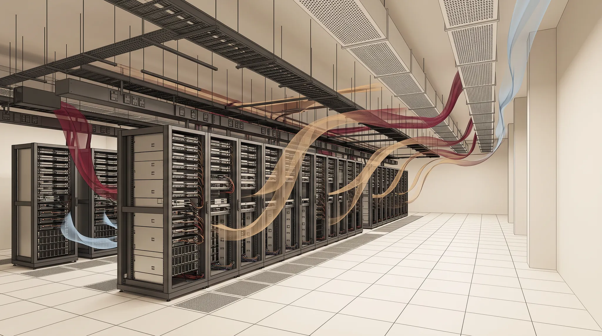
Data hall airflow
Evaluate supply distribution, return paths, rack inlet conditions, hot spots, recirculation, bypass air, pressure, and containment performance.
Computational fluid dynamics · data centers
Evaluate airflow, temperature distribution, cooling performance, recirculation, hot spots, failure scenarios, and equipment layouts before construction or operational change.
2,500+
international projects
70%
delivered for US projects
US + UAE
offshore delivery
LOD 100–500
model development range
Data center computational fluid dynamics modeling simulates airflow, heat transfer, pressure, and temperature conditions inside data halls and related spaces. A study can test rack and containment layouts, supply and return paths, cooling-unit performance, equipment loads, leakage, recirculation, failure conditions, and proposed design changes before construction or operational modification.
CFD results support engineering decisions; they do not replace the licensed engineer’s design authority, equipment selections, controls strategy, commissioning, or site verification. The study basis, assumptions, boundary conditions, load data, and acceptance criteria must be agreed before analysis.
Studies can be configured for design development, review, troubleshooting, resilience testing, retrofit planning, or documented comparison of alternatives.
Evaluate supply distribution, return paths, rack inlet conditions, hot spots, recirculation, bypass air, pressure, and containment performance.
Test agreed cooling-unit outages, load changes, redundancy scenarios, control assumptions, and temperature response against project criteria.
Assess external airflow and agreed dispersion scenarios around generators, exhausts, heat-rejection equipment, intakes, and nearby obstructions.
Review heat loads, ventilation, airflow paths, equipment clearances, local temperatures, and cooling or exhaust concepts.
Study airflow interaction, recirculation risk, ambient conditions, equipment arrangement, and performance constraints around heat-rejection systems.
Prepare geometry from coordinated BIM inputs, simplify it for simulation, track assumptions, and return findings into the design coordination workflow.
The delivery framework adapts to each sector’s information, coordination, documentation, and approval requirements.
Apartments, condominiums, multifamily, and residential developments.
Towers, offices, hospitality, retail, and mixed-use buildings.
White space, grey space, power, cooling, redundancy, and handover.
Manufacturing, utilities, equipment interfaces, access, and installation.
Hospitals, education, civic, and coordination-intensive facilities.
Site, civil interfaces, utilities, logistics, and model-based sequencing.
Regional delivery pages connect the service scope to local standards, sectors, and project controls.
National BIM and VDC delivery, with 70% of BIM Bots projects delivered for US work.
India-based BIM production, coordination, and QA/QC aligned to UAE project controls, consultant reviews, and Gulf working hours.
Specialist modeling and coordination for high-density, mission-critical systems.
Explore local delivery context across priority US hubs, the UAE, and Germany.
The study is only as reliable as its inputs, boundary conditions, scenario definitions, and engineering review.
Agree the question, scenario set, acceptance criteria, available data, design status, reporting needs, and responsible engineering reviewers.
Prepare geometry, loads, equipment and boundary conditions; document simplifications; then complete mesh and setup checks.
Solve agreed scenarios, check convergence and reasonableness, compare conditions, and identify sensitivities or unresolved inputs.
Issue visual results, assumptions, limitations, findings, and design considerations for review by the project’s responsible engineers.
Clear answers on scope, responsibility, standards, and project setup.
Typical inputs include coordinated geometry, room and rack layouts, IT and equipment loads, cooling-unit data, supply and return conditions, containment and leakage assumptions, controls intent, external conditions, and defined scenarios. The exact list depends on the decision being tested.
Yes, when the project team defines the failure case, operating sequence, loads, controls assumptions, duration, and acceptance criteria. Results should be reviewed with the responsible mechanical and controls engineers.
They can provide geometry and coordination context, but simulation models normally require simplification, cleanup, zone definition, boundary conditions, and engineering assumptions. A visually detailed BIM model is not automatically analysis-ready.
CFD analysis supports design decisions. Licensed engineering design, code compliance, equipment selection, controls, commissioning, and professional seals remain with the responsible project professionals unless separately contracted and verified.
Potential scopes include data halls, white space, grey space, mechanical rooms, electrical rooms, chiller or cooling-equipment yards, generator and exhaust areas, and agreed external dispersion conditions.
Start with the real constraints
Share the project location, sector, disciplines, required LOD, software, available inputs, first deadline, and known coordination risks.